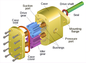
Xenon Gear Pumps are a type of Rotary Positive Displacement Pump. They consist of at least two separate and rotating gears with intermeshing teeth. As these meshed teeth separate, they create a partial vacuum which is filled by the fluid being pumped. As the gears then continue to rotate the fluid becomes trapped and is carried around the casing to the discharge side of the pump.
Here as the gear teeth begin to re-mesh the fluid is ejected creating a pumping action. There are a number of different Gear Pump designs but ultimately they all employ this same pumping principle. Note that contrary to common belief, pumps do not suck! Instead they create a partial vacuum within them which becomes filled or partially filled by the fluid which must be at a higher pressure for it to work.
The initial fluid pressure might be atmospheric or it maybe be greater or less than atmospheric depending upon the system. In effect the fluid is pushed into the pump as a result of this pressure difference between the outside and the inside of the pump.
External precision gear pumps are usually limited to maximum working pressures of around 210 bars (21,000 kPa) and maximum rotation speeds around 3,000 RPM. Some manufacturers produce gear pumps with higher working pressures and speeds but these types of pumps tend to be noisy and special precautions may have to be made.[3]
Suction and pressure ports need to interface where the gears mesh (shown as dim gray lines in the internal pump images). Some internal gear pumps have an additional, crescent-shaped seal (shown above, right). This crescent functions to keep the gears separated and also reduces eddy currents.
Pump formulas:
- Flow rate = pumped volume per rotation × rotational speed
- Power = flow rate × pressure
- Power in HP ≈ flow rate in US gal/min × (pressure in lbf/in2)/1714
Efficiency
Gear pumps are generally very efficient, especially in high-pressure applications.
Factors affecting efficiency:
- Clearances: Geometric clearances at the end and outer diameter of the gears allows leakage and back flow. However sometimes higher clearances help reduce hydrodynamic friction and improve efficiency.
- Gear backlash: High backlash between gears also allows fluid leakage. However, this helps to reduce wasted energy from trapping the fluid between gear teeth (known as pressure trapping).
Applications
- Petrochemicals: Pure or filled bitumen, pitch, diesel oil, crude oil, lube oil etc.
- Chemicals: Sodium silicate, acids, plastics, mixed chemicals, isocyanates etc.
- Paint and ink
- Resins and adhesives
- Pulp and paper: acid, soap, lye, black liquor, kaolin, lime, latex, sludge etc.
- Food: Chocolate, cacao butter, fillers, sugar, vegetable fats and oils, molasses, animal food etc.
- Aviation: Jet engine fuel pumps